Database Diagram (ERD) Design Tool for SQL Server
A database diagram tool allows you to visually design, analyze, and document SQL Server schemas. dbForge Studio for SQL Server provides this functionality through its Database Designer, an integrated ER diagram editor that enables you to create and manage SQL data model diagrams with ease.
With the Database Designer, teams can map relationships between tables, visualize dependencies, and maintain consistency across complex database structures. It bridges the gap between conceptual design and physical implementation, helping developers and architects plan, review, and adjust database schemas more effectively.
For detailed table-level editing, dbForge Studio includes a Table Designer: a tool for managing columns, indexes, and constraints. While the Database Designer visualizes entire schemas, the Table Designer fine-tunes each table's structure to align with the overall database ER diagram.
Put simply, you can use dbForge Studio for SQL Server to:
- Visualize database structures using entity relationship diagrams.
- Use containers to cluster logically related objects.
- Inspect logical relations between tables.
- Print out large diagrams.
- Create and edit database objects on diagrams.
- Reverse-engineer diagrams.
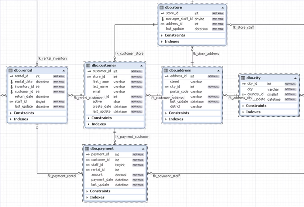
An entity relationship diagram (ERD) comprises a graphical representation of database structure and relationships between database objects. In other words, an ERD is used to sketch out the design of a database and illustrate its structure.
What's the difference between ER diagrams and ER models?
An Entity-Relationship (ER) model and an ER diagram are closely related, but they serve different purposes in database design. Understanding their distinctions helps developers and architects move smoothly from the conceptual stage of planning data to the physical structure in SQL Server. Let's explore them.
ER model:
- Defines the conceptual structure of data: entities, attributes, and their relationships.
- Specifies what information needs to be stored, not how it will be stored.
- Guides the early design phase by clarifying business logic.
Example: Showing that a Customer can place multiple Orders.
ER diagram:
- Visually represents that model in tools like dbForge Studio for SQL Server.
- Illustrates actual database objects such as tables, columns, and keys.
- Supports the implementation and maintenance of the physical schema.
Example: Displaying the Customers and Orders tables with a foreign key link.
In short, the ER model describes the logic behind your data, while the ER diagram in dbForge Studio for SQL Server shows how that logic is executed within a SQL Server entity diagram. Together, they form the foundation for efficient and scalable ER diagram database design.
How ER diagrams are used
Entity-Relationship Diagrams (ERDs) are used in the following ways within dbForge Studio for SQL Server.
Design databases
To design a database visually in dbForge Studio for SQL Server:
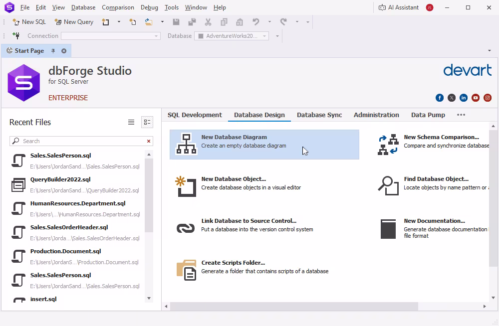
1. Open Database Diagram.
2. Drag and drop tables from Database Explorer.
3. Define primary and foreign keys to establish relationships.
4. Save the diagram to store your SQL Server data model.
This workflow helps you quickly create SQL Server database diagrams and refine them iteratively as requirements evolve. It's a clear, intuitive way to translate business logic into a working database structure.
Now that you know how to create ER diagrams in SQL Server, next, let's see what structural issues they help uncover.
Troubleshoot and monitor databases
ER diagrams are also powerful diagnostic tools. You can use diagrams to:
- Detect orphaned or unrelated tables.
- Spot missing foreign key relationships.
- Identify overlapping or redundant schema elements.
- Assess the overall structure and normalization level.
- Verify referential integrity across the database.
Put simply, teams can generate ER diagrams from SQL Server to debug real-world issues. Before problems affect performance, you can use the functionality of the SQL Server diagram tool to pinpoint and fix them.
Manage business information systems
ER diagrams are widely used for managing and optimizing business-critical databases such as CRM, ERP, or HR systems. For example, ERDs help architects manage HR systems by mapping user roles, permissions, and workflows visually.
Using tools like dbForge Studio for SQL Server, teams can easily edit SQL diagrams to update relationships or adjust data flows as business structures evolve, making it easier to see how employee data, access rights, and department structures connect across the organization.
Such database design diagrams provide a clear overview that simplifies auditing, system updates, and long-term scalability.
How to create a new database diagram in SQL Server
To create a new database diagram in SQL Server, you can use either SQL Server Management Studio (SSMS) or dbForge Studio for SQL Server. Both tools let you design tables and relationships visually instead of writing SQL code, making it easier to plan and manage your schema. Let's explore these two options.
Create a new database diagram using SSMS
SQL Server Management Studio (SSMS) includes a built-in SQL diagram editor that lets you design database schemas as diagrams and manage database relationships visually.
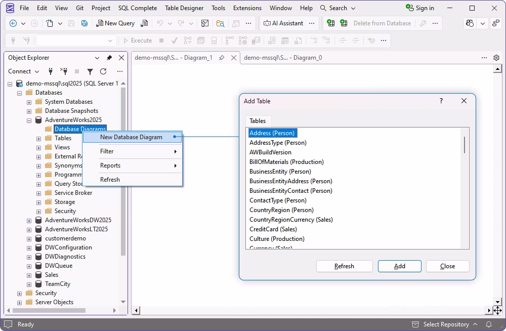
To create a new database diagram in SSMS:
1. Open SSMS and connect to your target database.
2. In Object Explorer, expand the database node.
3. Right-click the Database Diagrams folder and select New Database Diagram.
4. In the dialog that appears, choose the tables you want to include and click Add.
5. Arrange tables on the canvas as needed.
6. Go to File > Save Diagram, provide a name, and click OK.
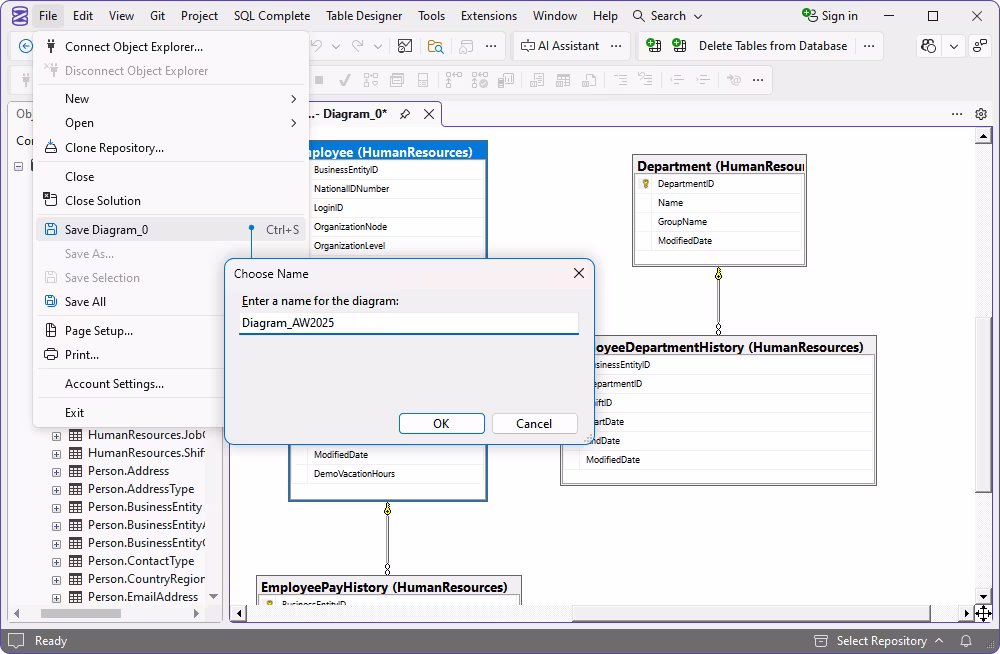
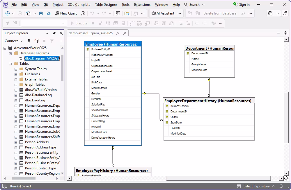
You can now view the saved diagram under the Database Diagrams folder in SSMS.
Generate a new database diagram using Database Designer
The Database Designer feature in dbForge Studio for SQL Server offers a more visual and flexible way to design and customize SQL diagrams than SSMS. It goes beyond the default capabilities of SSMS by letting you create SQL Server database diagrams faster while maintaining accuracy and visual clarity.
For anyone exploring how to create ER diagrams in SQL and wanting a clearer view of the differences between dbForge Studio and SQL Server Management Studio, the following table highlights their key features side by side.
| Features | dbForge Studio | SSMS |
|---|---|---|
| Visualize databases on diagrams | ||
| Access database objects for viewing their properties | ||
| Cluster logically related objects using containers | ||
| Create virtual relations and convert them into foreign keys | ||
| Automatically add all related tables onto a diagram | ||
| Create and edit tables on a diagram | ||
| Create and edit views on a diagram | ||
| Create and edit procedures on a diagram | ||
| Create and edit functions on a diagram | ||
| Search for an object on a diagram | ||
| Search text on a diagram | ||
| Create notes, stamps, images, and other elements | ||
| Customize diagram view with skins | ||
| Copy a database diagram image to the clipboard | ||
| Save a diagram in the database | ||
| Save a diagram as a file | ||
| Export a diagram to an image | ||
| Print a diagram | ||
| Navigate to an object in Object Explorer | ||
| Synchronize a diagram with Document Outline | ||
| Auto-arrange elements on a diagram |
How to create a database diagram in dbForge Studio
Creating ER diagrams in dbForge Studio for SQL Server requires no manual SQL coding. The built-in SQL Server diagram tool lets you design, review, and maintain databases visually. It is ideal for both new projects and existing schemas.
To create a new diagram using Database Designer, perform the steps below:
1. Open dbForge Studio for SQL Server and connect to the necessary SQL Server database.
2. Go to the Database Design tab and click New Database Diagram.
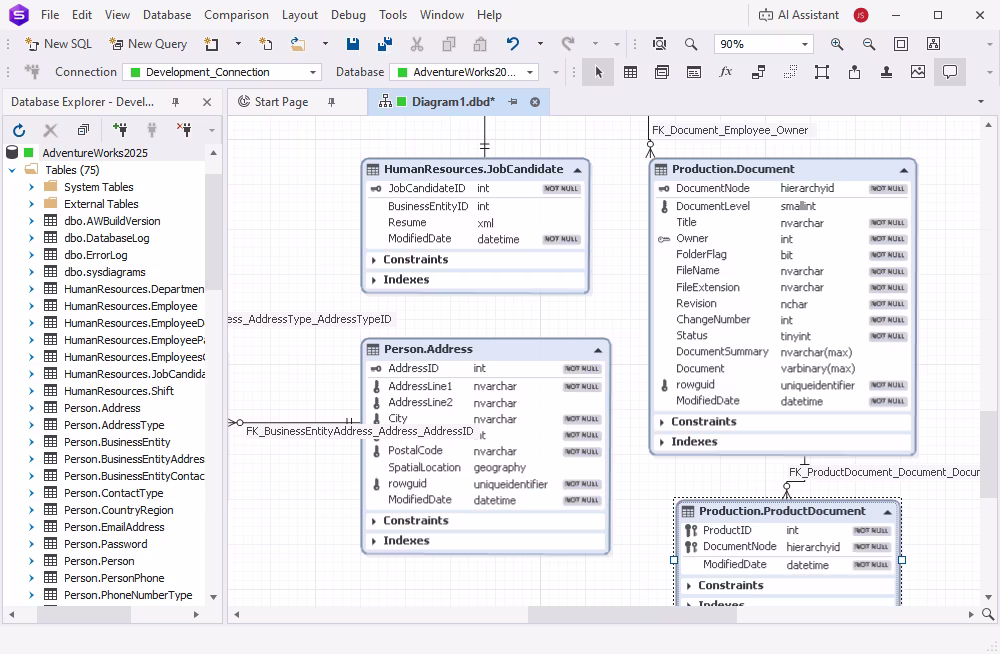
3. Drag and drop database objects from Database Explorer onto the ER diagram area. The database diagram will instantly display the objects and their relationships.
4. Define or adjust relationships as needed.
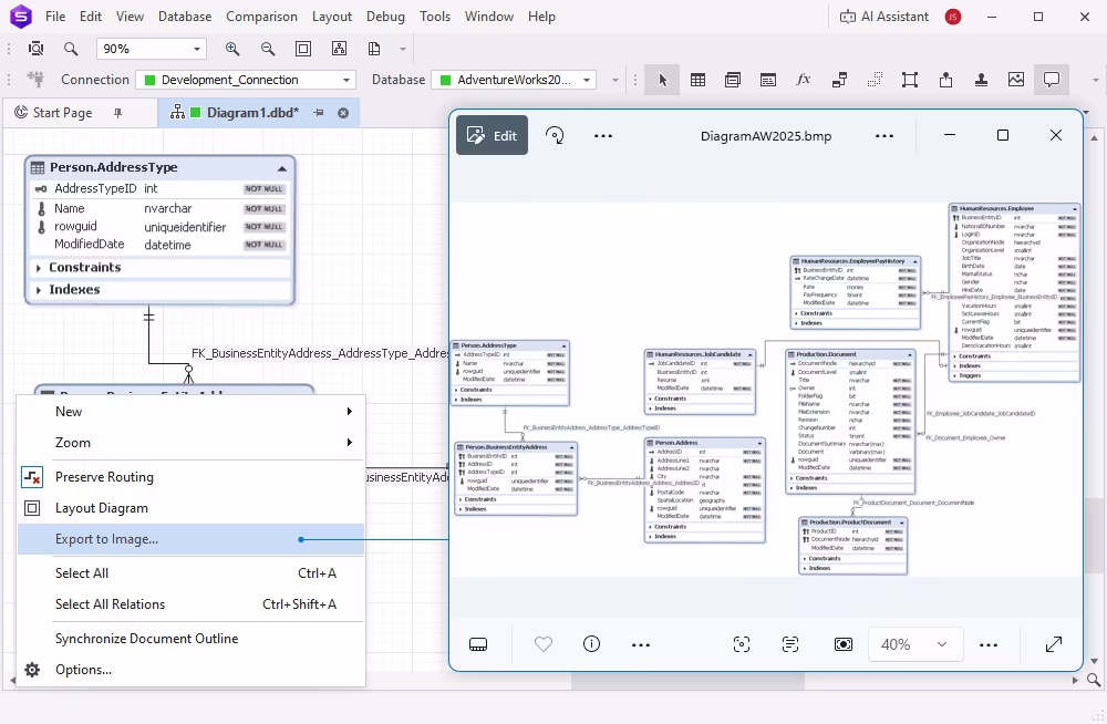
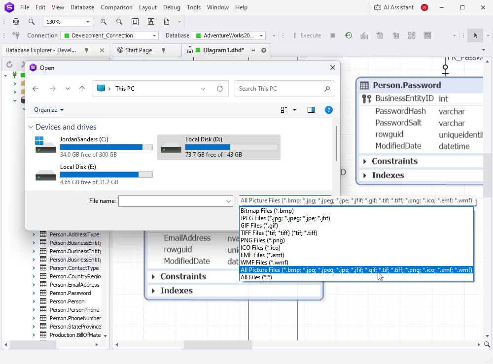
5. Save or export your diagram to an image format (BMP, JPG, GIF, PNG, TIF, or EMF).
To save a diagram, right-click the diagram background and select Export to Image from the context menu.
With this visual approach, you can generate ER diagrams from SQL Server in minutes, keeping your data model accurate, clear, and easy to maintain as your system evolves.
Create and edit database objects on a database diagram
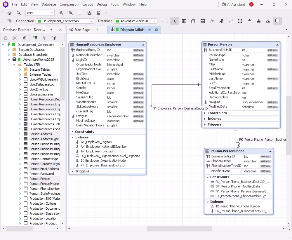
In dbForge Studio for SQL Server, you can visually manage your entire database structure, from building new tables to editing relationships, all within an interactive workspace.
Once your database design diagram is complete, dbForge Studio for SQL Server lets you build and modify database objects directly from the canvas. This visual approach helps maintain alignment between your logical model and the physical schema, eliminating the need for manual SQL scripts and keeping every change synchronized with your live schema. Let's walk through the processes of editing database objects.
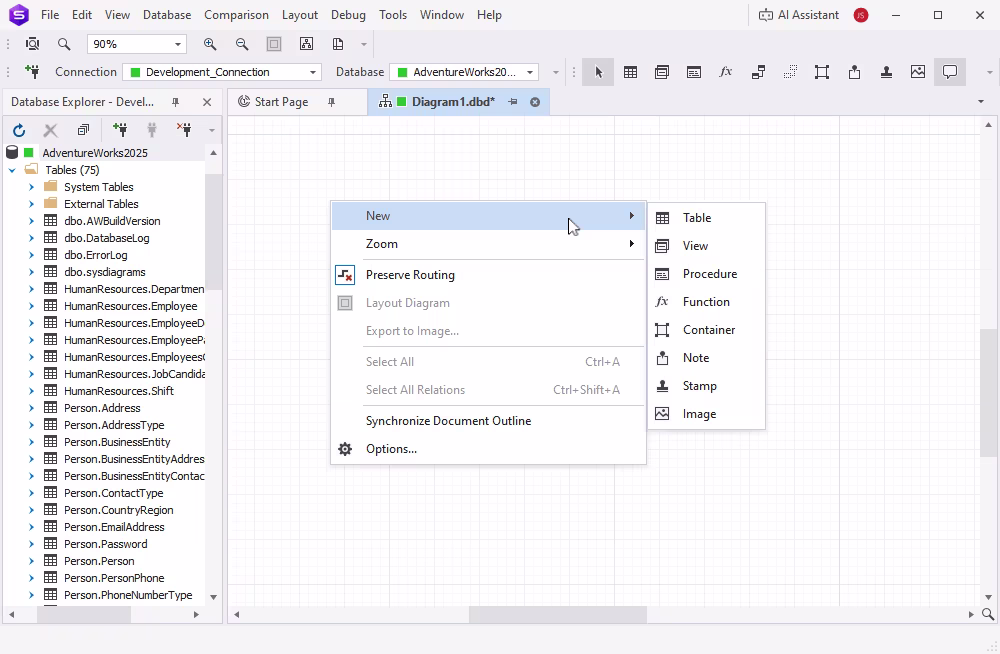
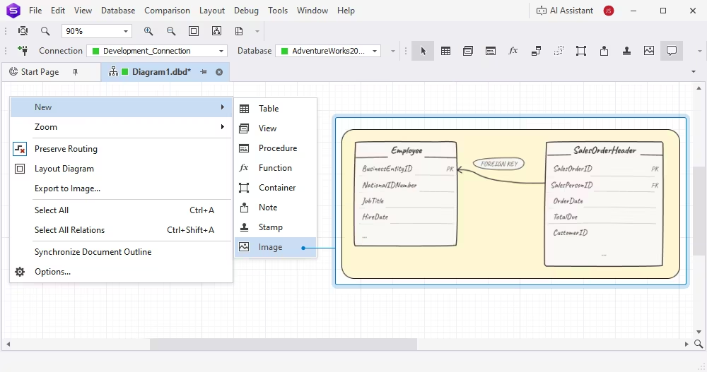
How to create objects and relations
To add new objects to your database design diagram:
1. Right-click the diagram area and select New > Table (View, Procedure, or Function).
2. The corresponding editor opens (for example, Table Designer for tables).
3. Define columns, data types, constraints, and indexes.
4. Click Apply Changes to update the database schema.
The selected object type opens in its dedicated editor, for example, Table Designer for tables or View Designer for views. After that, you can modify that object according to your needs.
Tip: To create a new foreign key visually, click New Relation button on the toolbar, drag from the child table to the parent table, and adjust the key properties in the dialog that appears.
If you need additional visual elements to enhance clarity and documentation, consider the following:
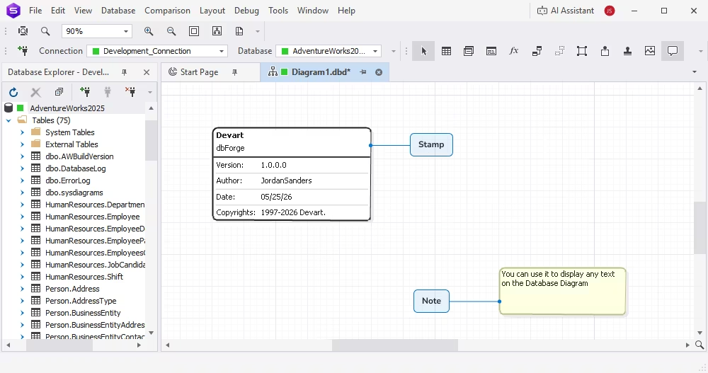
- Notes: Add comments or hyperlinks (e.g., to wiki pages with schema documentation) directly on the diagram.
- Stamp: Display diagram metadata such as author, company, version, or project name, useful for printed copies.
- Images: Add arbitrary images like sketches or design drafts to enrich your diagram and communicate context visually.
Tip: Use notes and stamps consistently across projects to make your diagrams easier to interpret for other team members.
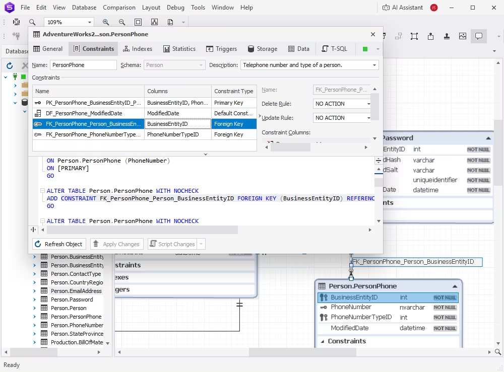
How to edit objects and relations
To edit SQL diagrams or modify existing objects on diagrams visually, refine the entire layout, and keep relationships organized. Here, we are going to examine how to edit database objects in a diagram with the help of dbForge Studio for SQL Server.
1. Double-click any table, view, or relation line on the diagram to open its editor.
2. Update column definitions, constraints, or key relationships.
3. Use the Properties panel to fine-tune details such as cascade options or referenced columns.
Click Apply Changes to confirm. Here is how you can edit SQL diagrams or modify existing objects with ease.
You can quickly rename the tables, change data types, or redefine foreign keys without switching to SQL code. This ensures your diagram and the physical schema stay aligned.
Tip: Use Document Outline to quickly find and edit foreign keys, ensuring consistency across large diagrams.
How to delete objects
To remove an element:
1. Select the table, view, or relation you want to delete.
2. Press Delete, or right-click and choose Remove from Diagram.
3. Confirm the action in the dialog.
Removing an object only deletes it from the SQL diagram view. To drop it from the actual database, right-click the object in Database Explorer and choose Delete. This gives you full control over how and when structural changes are applied.
Tune the design of a database diagram
With dbForge Studio for SQL Server, you can customize SQL Diagrams to make them more readable, consistent, and presentation-ready. Whether you're documenting complex systems or preparing layouts for collaboration, the built-in SQL diagram editor offers full control over appearance and structure. Using the editor, you can:
- Align shapes to organize tables and relations clearly.
- Adjust font sizes to improve readability.
- Customize colors and lines to highlight key relationships and areas.
These adjustments can be applied either globally to all diagrams or individually to a specific one.
Customize diagram options
To configure settings for the current diagram:
1. Right-click the diagram and select Options. In the Options dialog that opens, adjust parameters on the following tabs:
- General: Change background color, enable gridlines, or add shadows.
- Notation: Choose between predefined skins—Default, Simple, or IDEF1X.
- Page & Print: Configure page size, margins, and orientation.
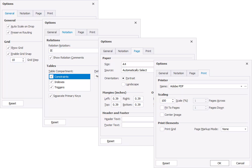
3. Click Reset anytime to restore default values.
Tip: The Default skin offers rich colors for on-screen work, while Simple and IDEF1X are optimized for printing and documentation.
Export SQL relationship diagrams
Once your database design diagram is finalized, you can easily export or save it for documentation, collaboration, or presentation purposes. dbForge Studio for SQL Server supports multiple image formats and layout options, making it simple to share your work visually with your team or clients.
To export the diagram, do the following:
- Click Export.
- Choose the desired format (PDF, PNG, JPEG, BMP, GIF, TIF, or EMF).
- Adjust layout options such as zoom level, grid visibility, or page orientation.
- Save locally to your preferred destination folder.
Tip: Exporting to vector format (EMF) ensures the best quality for large diagrams and printed documents.
If you encounter an error while exporting a large diagram (for example, "The image is oversized"), try one of the following fixes:
- Export to the EMF format instead of bitmap.
- Restart dbForge Studio to clear memory fragmentation.
- Use RAM optimization to free memory before exporting.
With these flexible options, you can export SQL diagrams and save ER diagrams from SQL Server in professional-quality image formats, ready to include in reports or share with your team.
Database diagram visualization tools
The database diagram visualization features in dbForge Studio for SQL Server make it easy to explore, understand, and refine complex database structures. It allows you to visualize SQL schemas clearly and efficiently, whether you're analyzing dependencies, reviewing relationships, or documenting your design.
Visualization features include:
- Zoom and pan: Navigate large diagrams smoothly with intuitive zoom and pan controls.
- Object coloring: Assign colors to tables, views, or groups of objects to highlight key entities or modules.
- Grouping by container: Organize logically related tables, for example, Orders, Customers, and Payments, within a single visual cluster.
In addition, dbForge Studio lets you use the following advanced view options for deeper control:
- Show or hide constraints, indexes, and triggers.
- Choose the level of field detail (column names only, names with data types, or full types).
- Display foreign key names next to relation lines for easier schema analysis.
- Use the Document Outline panel to navigate through all tables and relations in large diagrams.
Example: When visualizing a complex ERP schema, you can color-code HR-related tables in blue, finance tables in green, and logistics in orange. This helps teams quickly identify related objects within the same diagram.
These options make it easier to visualize SQL schemas, maintain clarity in large projects, and keep your database diagram visualization well-organized for collaboration or documentation.
Clustering logically related objects
When working with large and complex databases, it can be difficult to keep track of related entities. dbForge Studio for SQL Server simplifies this with diagram containers, which allow you to group tables in SQL diagrams based on their logical or functional relationships.
Using SQL Server diagram containers, you can:
- Organize related objects, for example, cluster Orders, Payments, and Customers tables together for clarity.
- Collapse or expand containers to focus on specific parts of your database.
- Rename containers to describe their purpose (e.g., Sales Module or User Management).
Example: In a CRM system, you can create one container for Accounts and Contacts, another for Invoices and Payments, and a third one for Support Tickets. This modular view helps teams quickly understand dependencies without being overwhelmed by hundreds of objects on a single canvas.
By grouping related elements logically, you can maintain a cleaner and more scalable SQL Server database diagram, making collaboration and analysis much more efficient.
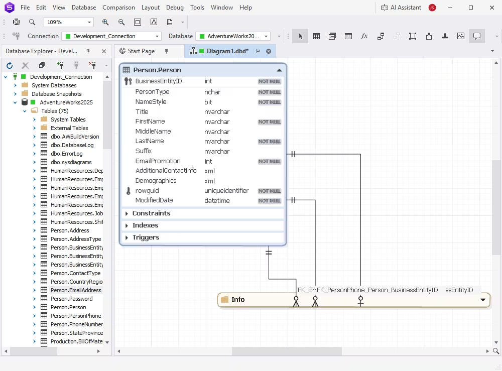
Tracking logical relations between tables
Understanding how tables connect is essential when managing large or complex databases. dbForge Studio for SQL Server makes it easy to track table relationships in SQL visually through both physical and virtual relations displayed on your diagram.
Here is how you can do it:
- Enable key lines in settings: Right-click the diagram > Options > Relations to toggle primary and foreign key lines.
- Hover over fields to highlight related entities: The platform automatically emphasizes all linked tables in your SQL foreign key diagram, helping you trace dependencies instantly.
- Use color cues: Primary keys are typically underlined, while foreign keys appear with connecting lines for quick identification.
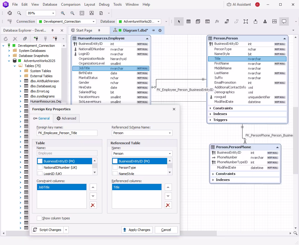
- Access relation details: Double-click a relation line to open Foreign Key Properties and review or edit constraint settings.
Tip: For tables without existing foreign keys, you can create virtual relations that represent logical connections. These can later be materialized into real database constraints through the Virtual Relation Manager.
This visual workflow helps you quickly track table relationships, identify missing keys, and maintain referential integrity across your entire schema.
Printing a diagram
dbForge Studio for SQL Server allows you to print SQL diagrams directly from your workspace, making it easy to create physical documentation or share designs in meetings and reports. You can configure printing options to ensure your diagram fits neatly across pages without losing detail or readability.
To print:
- File > Print Setup
- Choose the orientation (Portrait or Landscape)
- Click Print
You can further customize print settings to match your layout requirements when you:
- Set page margins, size, and source for precise output.
- Adjust scaling to fit large diagrams across multiple sheets.
- Enable print markup to display grid boundaries and page divisions.
- Center the diagram on the page for balanced alignment.
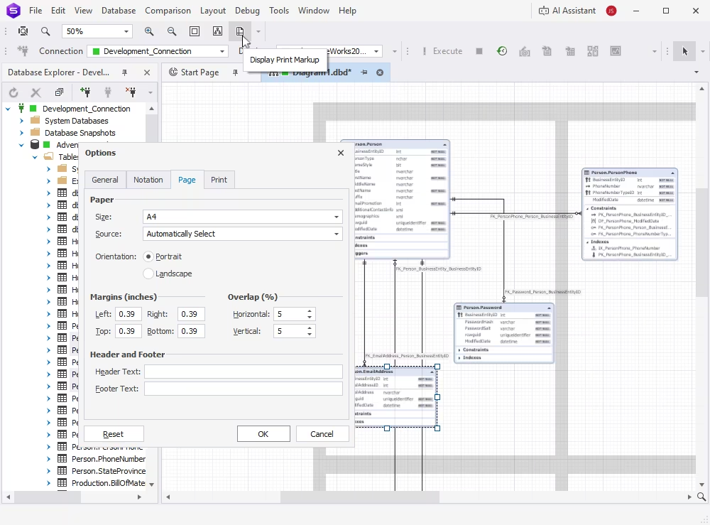
Tip: Use Print Preview to check alignment and scaling before printing. This is especially useful for large or complex ER diagrams.
With these options, you can easily print ER diagrams in SQL Server from dbForge Studio for SQL Server, ensuring your visual database documentation looks professional and complete.
Searching text on a diagram
When working with large diagrams, quickly locating specific tables, columns, or constraints becomes essential. dbForge Studio for SQL Server includes a convenient search feature that helps you instantly find objects in SQL Server diagrams without manually scanning the canvas.
To search:
- Press Ctrl + Shift + F.
- Enter the object name (for example, a table, column, or constraint).
- Click Find All.
- Double-click an object in Find Results to navigate to it on the diagram.
You can also search SQL diagrams by related elements such as:
- Column names, indexes, and constraints.
- Stored procedure parameters and function names.
- Text inside notes, stamps, relation comments, and container names.
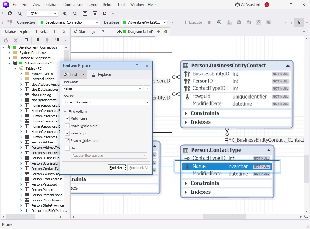
Tip: Use partial keywords when unsure of the exact name; the Studio will highlight all potential matches in real time.
This feature saves time when managing complex database design diagrams, ensuring you can locate, review, and update schema components efficiently.
Using additional diagram elements
Beyond tables and relationships, dbForge Studio for SQL Server lets you enrich your database design diagram with visual and descriptive elements that improve understanding and documentation. These additions make your diagrams more informative and easier to interpret during design reviews or audits.
Here are the most common ones:
- Notes: Capture design assumptions, clarify relationships, or document key decisions directly on the canvas to keep all context in one place.
- Virtual relations: Simulate logical connections between tables that don't yet have foreign keys. This helps visualize dependencies before implementing them in the schema.
- Images: Add branding, legends, or visual guidance for teams reviewing your diagram. Supported formats include BMP, JPG, GIF, PNG, TIF, and EMF, giving flexibility for both vector and raster graphics.
You can also include stamps to display metadata such as diagram author, company, project version, or creation date. These are ideal for maintaining traceability across different project iterations.
With these enhancements, you can add annotations to SQL diagrams that bring clarity and context to your database models, turning them into complete, self-explanatory design assets.
Tip: Use SQL diagram notes to highlight unique constraints, relationships, or future design changes. Consistent annotations make collaboration easier and reduce the need for external documentation.
Using reverse engineering to create database models from existing databases
Reverse engineering in dbForge Studio for SQL Server allows you to generate a database model or ER diagram from an existing database without writing any SQL code. This process helps you create ERDs from databases, visualize dependencies, and document existing structures efficiently.
Steps to reverse engineer:
1. Connect to SQL Server.
2. Go to Database > New Diagram.
3. Select the required tables and confirm.
This creates a visual ER diagram based on the existing schema, allowing you to explore relationships, constraints, and dependencies interactively.
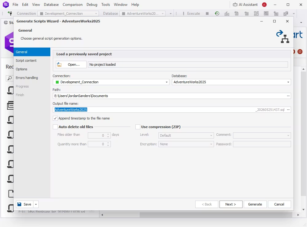
For more advanced reverse-engineering tasks, such as exporting the entire database structure or generating schema scripts, you can use the Generate Scripts Wizard. To do this:
1. Go to Database > Tasks > Generate Scripts.
2. Set the required connection and database, specify the output path and file name, and adjust additional options.
3. Click Generate to export your schema.
You can also create a scripts folder or snapshot for documentation and version control, each serving a specific purpose:
- A scripts folder contains SQL files representing your database schema.
- A snapshot is a single XML file that stores the structural metadata of your database.
To generate them:
1. Go to Database > Tasks > Create Scripts Folder or Snapshot.
2. Choose the source type (database or snapshot).
3. Define the destination path and click Create to launch the generation.
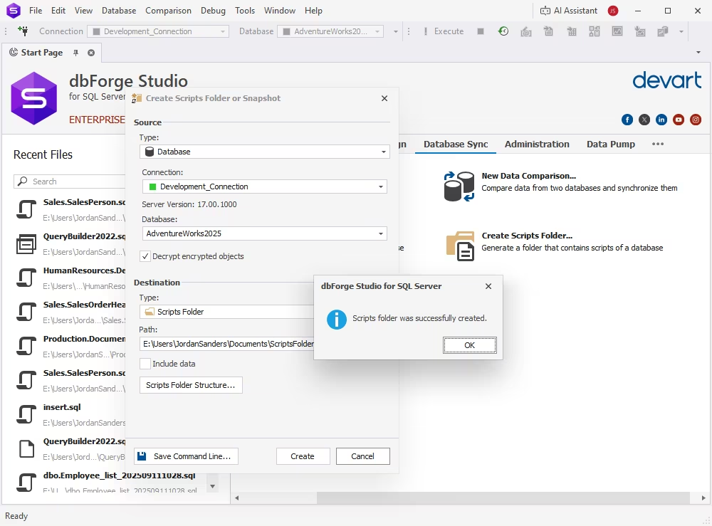
For automation, use the Save Command Line option to generate CLI scripts, perfect if you want to reverse engineer SQL Server processes into CI/CD workflows or scheduled backups.
Tip: Use reverse engineering whenever you inherit a legacy system or need to document existing databases for audit, migration, or design review.
Using forward engineering to create a database
Forward engineering in dbForge Studio for SQL Server allows you to generate a new database directly from your database model. This process is ideal for teams that want to forward-engineer SQL diagrams into ready-to-use SQL Server databases.
Steps to forward engineer a database
Start by creating an empty database to host your model:
1. Open dbForge Studio for SQL Server and navigate to Database > New Database.
2. Enter the database name, choose the owner from the drop-down list, and add a description if needed.
3. Click Apply Changes to create the empty database.
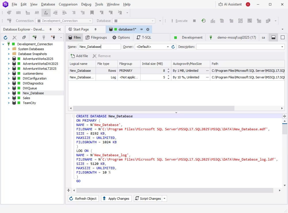
4. Click Refresh in Database Explorer to see the newly created database.
Link to source control and deploy schema
After the database is ready, link it to your stored schema to apply the structure automatically. Do the following:
1. Right-click the new database and select Source Control > Link Database to Source Control.
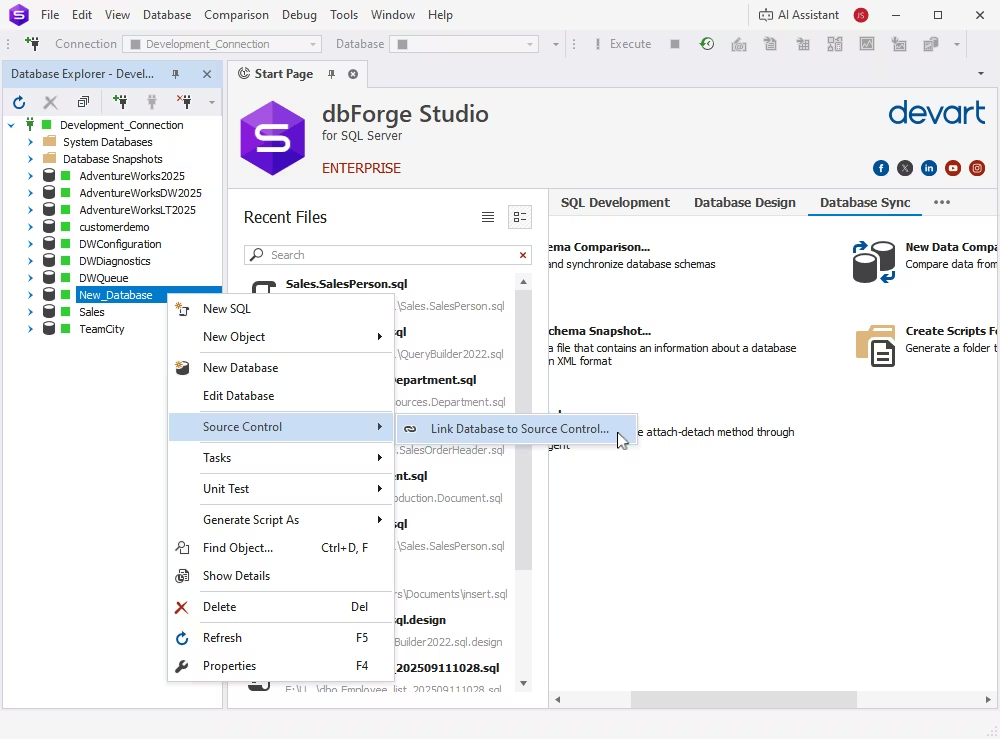
2. Click the plus icon in the Source Control Repository field and select the scripts folder you created earlier using the Create Scripts Folder or Snapshot option.
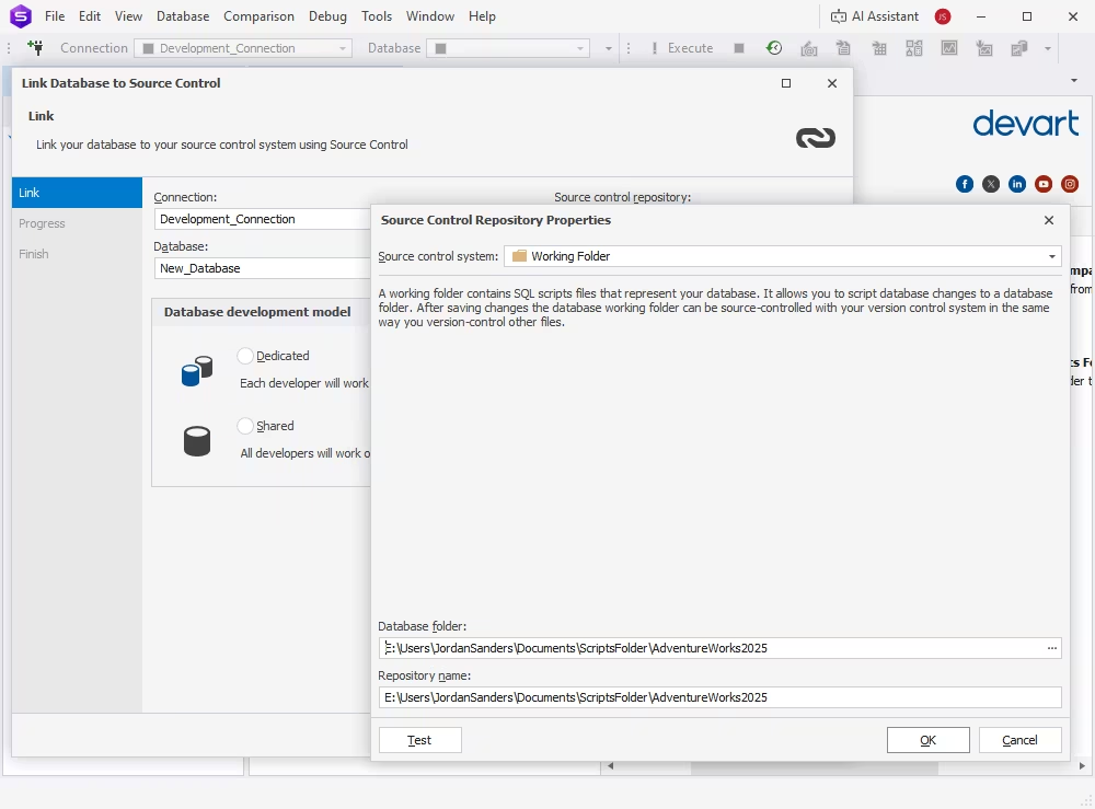
3. Choose the appropriate development mode, then click Link.
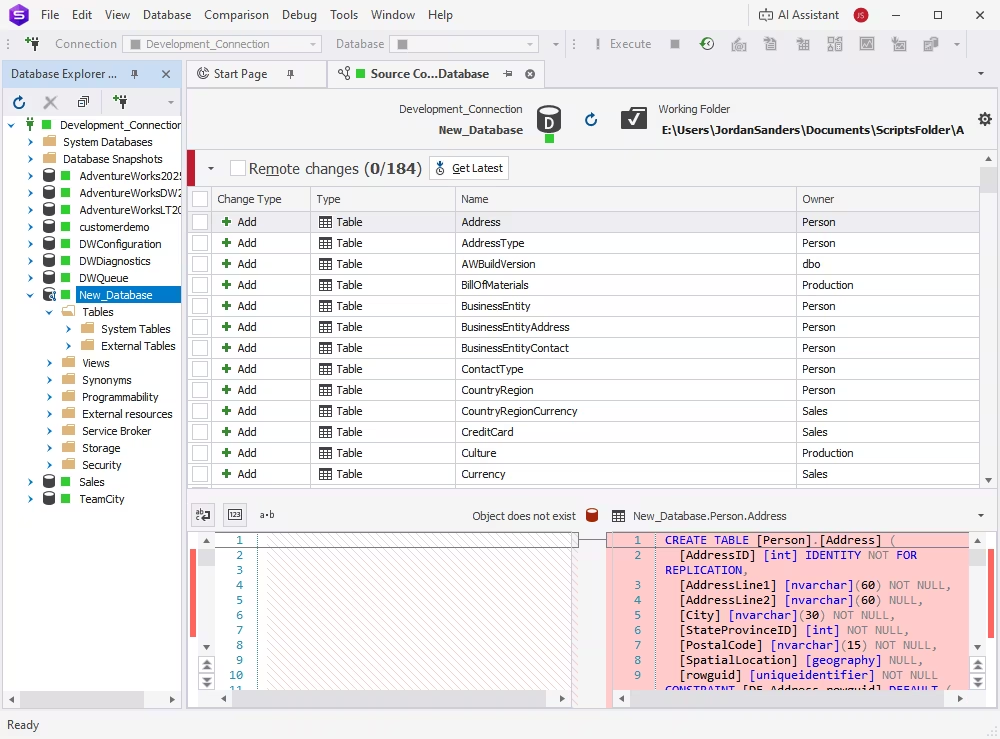
4. Once linked, dbForge Studio displays all objects available for forward engineering.
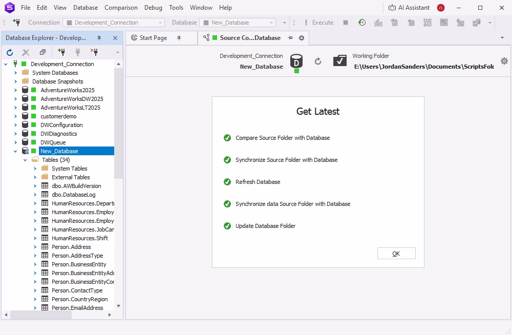
Generate or deploy a schema
To populate the database, you can use one of the two available options:
1. Select Remote changes and click Get Latest, all objects will be deployed to your SQL Server instance.
2. Alternatively, generate SQL scripts (DDL) or deploy directly via the Publish feature for immediate implementation.
Tip: Use forward engineering to generate databases from diagrams and maintain a smooth connection between your visual design and the deployed schema.
Final word
ER diagrams remain fundamental to designing and maintaining reliable SQL Server databases. They give teams a clear view of how tables connect, where dependencies exist, and how structures should evolve as systems grow. With a well-built diagram, architects and developers can plan changes confidently, avoid structural issues, and keep database design aligned with business requirements.
dbForge Studio for SQL Server strengthens this process by providing a complete visual environment for modeling, editing, and synchronizing database schemas. Its integrated Database Designer makes it easy to work with complex structures, generate accurate documentation, and move smoothly between conceptual design and live deployment.
Try dbForge Studio for SQL Server and simplify your ER diagram workflow today.
FAQ
A database entity relationship diagram in SQL Server visually represents how tables, keys, and relationships connect. It's the foundation of clear database design that helps teams maintain accuracy and consistency when they need to manage complex systems.
In dbForge Studio for SQL Server, you can generate an ERD diagram automatically from any existing database. Simply connect to your SQL Server, go to Database > New Diagram, select the required tables, and the tool will visualize the relationships instantly.
To create a SQL ER model in SSMS, open Object Explorer, expand your database, right-click the Database Diagrams folder, and choose New Database Diagram. Add your tables, arrange them visually, and save your design for future use.
In dbForge Studio for SQL Server, editing database ER diagrams is fully interactive. Double-click a foreign key line to change its properties, reroute connections for clarity, or hide comments you don't need. Every visual update can be synchronized back to the live schema with a single click.
dbForge Studio for SQL Server allows you to export your SQL data model diagram in multiple formats, including PDF, PNG, JPG, GIF, and TIFF. Simply right-click the diagram, select Export to Image, choose your preferred format, and save it locally for documentation or sharing.
An ER model defines data conceptually, what entities and relationships exist, while a database ER diagram shows how those elements are physically structured. dbForge Studio for SQL Server bridges both: it lets you design conceptually and implement visually.
dbForge Studio for SQL Server delivers a comprehensive ER diagram database design experience. Key features include visual editing, automatic relationship mapping, forward and reverse engineering, schema synchronization, and export options for images and documentation.
You can compare diagrams in dbForge Studio for SQL Server using the SQL Server entity relationship diagram view. By linking to Source Control or comparing database snapshots, the tool highlights structural differences (such as modified tables, relationships, or keys) to simplify schema version tracking.
Yes. With dbForge Studio for SQL Server, any database relationship diagram can be translated into executable SQL scripts. Use Generate Scripts Wizard to create schema DDLs that can be reviewed, versioned, or deployed to another SQL Server instance.
A SQL entity relationship diagram provides a visual map of how tables connect, helping designers identify redundancies, enforce data integrity, and plan normalization. It's an essential tool for refining database architecture before implementation.